I. Background of the project
Most densely packaged electronic enclosure systems use fans or drum fans for forced air cooling. Smaller chassis systems typically use axial cooling fans, where the airflow is perpendicular to the fan blades. However, larger chassis systems may require centrifugal drum fans to provide sufficient airflow at high static pressures.
At the earliest stages of chassis system design, engineers should determine a prediction of forced air cooling airflow requirements. More importantly, the product design phase must provide good airflow for the heat-generating components and adequate space and power for the cooling fans.
Factors to consider in fan selection include required airflow, AC or DC power, voltage, speed, life expectancy, EMI/RFI, heat dissipation, automatic restart and noise impact.
The initial stage of product design is to anticipate the airflow volume required to ventilate and cool the enclosure system, largely dependent on the heat generated within the enclosure system and the maximum allowable temperature rise of the device.
When estimating the heat dissipation within the chassis system, the possibility of a change in device load or an increase in heat dissipation of the heat-generating sub-chassis system should be considered. Therefore, the worst-case scenario of a fully-loaded chassis system should be used to estimate the airflow required for the chassis system using the maximum heat dissipation.
The airflow required for the chassis system can be obtained by the following formula or from a chart, calculated as
Here.
Q=1.76W/T
Q = airflow required in cfm (ft3 / min.)
W = heat consumption in watts.
TC = Temperature rise
For example, for a chassis system with 200W of heat consumption, if its allowable temperature rise is 20°C, then the chassis system requires 17.6 cfm of airflow.
In the figure below, the vertical axis represents the heat dissipation to be carried away by the representative airflow, and the horizontal axis represents the airflow’s air volume; both axes are logarithmic. The sloping lines define the temperature rise (°C). By looking up the graph, find the diagonal line that represents the allowable temperature rise and then, on that line, finds the point that corresponds to the heat dissipation; the position of the horizontal axis corresponding to this point is the required airflow for the enclosure system.
Second, the chassis system impedance.
Determining how to install a fan within an enclosure system is much more difficult than calculating the required airflow. Obstructions in the airflow path cause static pressure resistance. The graph below shows the non-linear relationship between airflow and static pressure for a typical fan. To achieve maximum airflow, obstructions should be minimized. However, sometimes additional baffles are required to direct cool airflow to the components that need cooling. Of course, the chassis system components themselves can obstruct airflow and direct airflow.
Experimental methods to obtain the flow rate of airflow are very accurate, but the tests are costly, time-consuming and cumbersome. Moreover, it is almost impossible to find large airflow chambers for performing measurements.
In practice, empirical methods are commonly used to estimate airflow resistance. Experience has shown that.
① Empty boxes usually reduce airflow by 5% to 20%.
② Dense enclosure systems can reduce airflow by as much as 60% or more.
③ In water, most electronic enclosure systems have a static pressure between 0.05 and 0.15 inches of the water column.
For a dense chassis system enclosure, the fan in the previous example should be able to provide 80 cfm of air, not 32 cfm.
III. Measuring airflow and static pressure
The AMCA Standard 210 Dual Airflow Chamber can be used to accurately measure airflow volume and static pressure.
List of equations and variables
Q: Airflow = Picture
C. Nozzle airflow coefficient
D: Nozzle diameter (m)
r: Air density = Picture
T: Temperature (℃)
P: Air pressure (mm Hg)
Pn: Differential airflow pressure (mm Aq)
Ps: static pressure (mm Aq)
g: Pictures
Maximum static pressure and maximum airflow measurements must be performed separately.
Maximum static pressure measurement: When the nozzle is closed, the pressure in chamber A will reach its maximum value. The pressure difference Ps represents the maximum static pressure that can be reached by the fan.
Maximum airflow measurement: Open the nozzle and use the auxiliary blower fan to reduce the pressure in chamber A to Ps = 0. The maximum airflow can then be calculated using Pn, D and the airflow equation above. Q represents the maximum flow rate the fan can achieve in free air.
Four, the fan of the chassis system working points point and air duct recommendations
The performance of a fan is determined by the intersection of the air resistance PQ characteristic curve of the chassis system and the P-Q characteristic curve of the fan. The characteristic fan curve is explained in the section on measuring airflow and static pressure. When the chassis system structure is fixed, the PQ characteristic curve of the chassis system is fixed. It describes how air flows through the chassis system with specific obstructions and internal resistance. The flow resistance is roughly proportional to the square of the volume flow rate. Thus, the graph of static pressure versus airflow in a chassis system is a quadratic parabolic shape. This curve can be easily obtained experimentally by testing the pressure difference between the inlet and outlet of the enclosure system at various airflow rates.
The full potential of the fan can only be realized by designing the optimal placement of the fan and optimizing the chassis system air ducts. Otherwise, the characteristic fan curve is suppressed, resulting in reduced airflow. Some recommendations for chassis system air ducts to minimize the resistance loss of the chassis system follow.
These calculations or recommendations are based on 4715 series fans; however, it applies to other fans as well. The graph below shows the compression of the characteristic fan curve caused by an obstruction near the fan inlet or exhaust port. X is the distance from the fan to the obstruction.
Probes that measure air pressure will produce less resistance loss and will make more noise if placed at the outlet. Placing an obstruction near the fan inlet may cause more noise than placing an obstruction at the fan outlet.
Five, choose the fan.
By estimating the required airflow, you can select a specific fan. First, consider whether the fan should use AC or DC power. DC fans are more costly, so chassis systems almost exclusively use AC fans. Now that this price difference has disappeared, the many advantages of DC fans make them the best choice. One advantage of DC fans is their longer life span, and another is that power consumption is nearly 60 percent lower than AC fans. According to industry experts, a 10°C increase in fan temperature can reduce their service life by as much as 20,000 hours.
Another selection factor is that the speed of a DC fan is directly proportional to the voltage, so it can run at a reasonable airflow requirement. However, usually, the fan runs below the maximum speed, which in turn is quieter and less powerful.
Other advantages of DC fans include lower EMI and RFI than AC fans. In addition, with AC fans, designers have to deal with a wide range of supply voltages and frequencies. When using DC fans, these problems disappear. Overall, using a DC fan is easier than an AC fan.
Most DC fans are available in both 12V and 24V versions. The higher voltage is preferred because it results in lower current and lower power consumption.
The frequency and amplitude of noise generated by the fan increases as the speed increases. If you have a choice, select a low-speed motor to reduce noise.
After estimating the airflow requirements and static pressure of the chassis system, you can consult to find the fan PQ curves provided by the supplier to select a fan that will provide adequate cooling airflow. Engineers should use these curves with caution, as the true PQ performance curve of a fan may vary by as much as 10% from the performance of the nominal curve shown.
Sometimes testing fan performance data in free air that is not properly configured can lead to some errors. Such errors are approximately between 0.05 and 0.15 inches of the water column.
Noise has no effect on the cooling of the fan but is very important to the chassis system and the user. The quietest fan possible should be selected, and steps should be taken to reduce fan noise.
One way to reduce noise is to use the largest fan possible. For a given airflow, a larger size fan runs at a slower speed and therefore produces less noise.
As mentioned above, DC fans generate much less EMI and RFI than AC fans. For routine applications, EMI and RFI from fans are not a problem. However, EMI and RFI can be a serious problem if the equipment is operating in an interference-sensitive environment.
Six, fan life
Bearing wear is a major factor in fan life. Most fan manufacturers use similar bearings, so there is not much difference in the bearings. Most manufacturers promise a life of 50,000 hours; at 40 hours per week, this equates to 25 years. Therefore, a fan is likely to last longer than the equipment it cools. As mentioned earlier, the temperature of the fan will decrease significantly as the temperature increases.
UL requires that the fan must be able to withstand a locked rotor for 72 hours (15 days for AC fans) without causing any damage and without overheating. The fan must also be able to restart and operate properly after eliminating the cause of the locked rotor.
The impedance limits the current in the AC fan winding, but the DC fan requires an electronic lock on the rotor to limit the current during failure. Several types of protection are currently in use, but not all provide automatic restart. Chassis system designers should carefully evaluate fan protection types to ensure that DC fans automatically restart after removing an obstruction. They should also ensure that the protection enclosure system operates well during intermittent power interruptions.
Seven, the air intake (blower) or exhaust (extraction)?
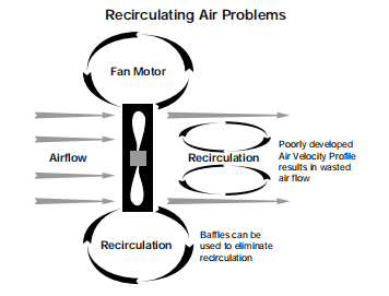
Designers can choose to install fans to exhaust hot air from the chassis system or to blow cool air into the chassis system. In theory, the same amount of air is used to dissipate heat, whether it is extracted or vented. In practice, however, there are advantages and disadvantages to each arrangement. The air sucked into the fan is laminar flow. The laminar flow pattern will distribute airflow velocity evenly throughout the chassis system. This is important to eliminate stagnant air (vortex areas) and local temperature hot spots.
The air exiting the fan is turbulent. The heat transfer in turbulent airflow can be twice that of laminar flow with the same volume flow. However, in general, the area of turbulent airflow near the fan exhaust opening is very limited, so it is critical to developing a well-designed airflow path for the entire enclosure system. The area of the vent should be at least 50% larger than the fan opening.
Care must be taken to eliminate air recirculation in the fan, i.e., the backflow of hot air from the fan outlet. Many airflow cooling properties can be lost due to airflow recirculation problems. Baffles can be used to eliminate the recirculation backflow phenomenon of air. The airflow path must be the path of least resistance.
Subassemblies and components within the enclosure system should be placed where airflow can be directly cooled and placed to take advantage of natural convection cooling as well—place high-temperature components in the upstream direction of cooler components. Avoid placing large size components that block the airflow to smaller size devices. If necessary, baffles must be used to direct the airflow to the higher temperature devices.
The extraction fan may cause the pressure inside the enclosure system to decrease and airborne dust to be drawn inside the enclosure system through all vents and cracks in the closed enclosure system.
If the chassis system requires dust removal, it is best to use a fan that blows air into the chassis system, i.e., a drum fan. In this configuration, a filter at the fan inlet removes dust from the incoming air. Another benefit is that a positive airflow pressure zone will be generated inside the chassis system; this way, dust will not flow into the chassis system from the surrounding environment, but the filter must be replaced periodically to eliminate accumulated dust. Dust buildup can severely restrict airflow, which can lead to higher temperatures in the air and devices in the chassis system.
Another disadvantage of the blower fan is that the heat generated by the fan motor will enter the interior of the chassis system, which will inevitably reduce the cooling efficiency of the air. For this type of reason, devices that are more sensitive to temperature or are not heat resistant should be located close to the fan inlet.
In many applications, using a blower fan instead of an extract air fan can double or triple the life of the fan. Hot air will flow through the fan and inevitably affect the life of the fan, while a blower fan with an inlet air temperature of 25°C will have a much longer life than an extract fan. As shown in NMB’s “Warranty Statement” and “Fan Life Derating Curve,” a decrease in temperature has a significant effect on fan life.
Eight, noise impact
Most designs require minimal fan noise to meet the user’s need for a quiet chassis system. Accordingly, this inevitably requires smaller chassis system sizes and higher operating performance, both of which increase the demand for airflow through the chassis system, which in turn increases noise.
Mechanical noise can be caused by vibrations in the bearings or unbalanced rotation of the blades. If this vibration frequency matches any resonant frequency of the chassis system, it can be amplified to intolerable, even destructive, levels. Motor motors also generate noise; however, this is a small part of the noise generated by the cooling enclosure system.
All of these noise components are inherent in fan design and are almost entirely beyond the control of the chassis system designer. But there are a few details or suggestions that can help chassis system designers minimize noise.
① Avoid placing obstacles in the area of high wind speed close to the fan.
② Use vibration isolators to eliminate the transmission of mechanical noise from the fan to the chassis system.
③ Use reinforced structures to control the resonant frequency of the chassis system.
④ Install the fan on the inner surface of the chassis system instead of the outer surface.
⑤ Obstacles placed near the fan inlet produce more noise than those placed near the fan outlet.
Designers should be very careful when comparing the noise specifications of different fan manufacturers. Although a standard noise measurement method has been proposed, it has not been accepted by all fan manufacturers and users, and that method is the ANSI 1211 method.
Nine, the joint use of multiple fans
Despite your best efforts, an “extra cooling” condition may arise after the design is complete. To deal with this condition, you should first select a specific size of low or medium airflow fan. Then, if more cooling air is needed, it is easy to replace the existing fan.
In contrast, if the initial choice of fan performance is high, then the “extra cooling” needs to be considered, and the structural layout of the chassis system must be redesigned.
When additional cooling is considered, and a higher performance fan of the same size cannot be used, four options can be considered.
①Improve the airflow organization within the chassis system.
② Redesign the chassis system to use larger fans.
③ Modify the chassis system to use two or more fans in parallel.
④ Modify the chassis system to use two or more fan series.
Often, adequate additional cooling can be provided by improving the airflow organization within the chassis system or by changing the location or size of the vents. If you cannot improve by modifying airflow, then the preferred solution is to modify the chassis system to accept a larger fan. This allows the selection of a fan that matches the requirements of the chassis system. Sometimes, however, this option is not possible. Fans with adequate performance may not be available, or larger fans may be prohibited due to size constraints. These situations require one or more additional fans.
In some cases, additional fans are used to increase the airflow within the chassis system. In addition, standby fans can be designed to improve chassis system reliability.
But an additional fan can create problems. It doubles the cost, doubles the noise, doubles the heat generated by the fan, and may provide little improvement to the cooling of the system.
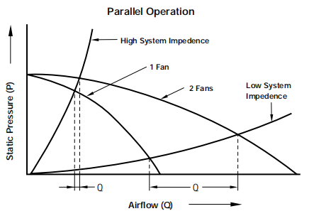
Modification of wind turbine parallel P-Q curve
The two fans in parallel double the airflow only in free air situations. If the enclosure system has high static pressure, this arrangement will increase the flow less. Two fans in series will double the static pressure but will not increase airflow in a free air situation. Fans in parallel can increase airflow at low static pressures and then make the fans in series, which can further increase the static pressure of the fans.
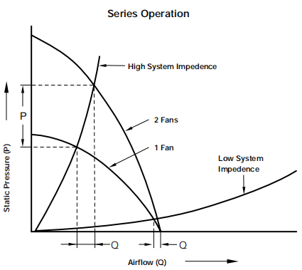
Modification of P-Q curve for fan tandem
In addition, the thermal impact of multiple fans connected in parallel and in series on the chassis system itself cannot be ignored.